Types of Rigid-Flex PCB Stackups Used in Fabrication
Rigid-Flex PCB Stackups Used in Fabrication
Rigid flex PCBs are used in a wide range of applications and provide benefits like dynamic bending, vibration and shock resistance, and weight reduction. These advantages make them a popular choice in medical, automotive, aerospace, and military electronics that require reliable field operation. Rigid flex PCBs also have a number of unique fabrication considerations that differ from traditional rigid PCBs. The following article examines the various types of rigid-flex PCB stackups that are used in fabrication.
Using the rigid sections of the rigid flex pcb fabrication as a base, manufacturers then add a layer of flexible material to the center of the board. The flexible section enables the circuit to bend around corners and other difficult to reach areas. To help with this, the layer of flex material is usually covered by a protective plastic or resin. This helps protect the conductive copper layers, which may be vulnerable to damage during assembly and operation.
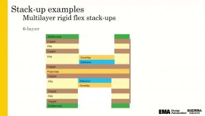
The next layer in the stackup is a layer of insulation, which acts as a barrier between the conductive copper layers and the flexible section. Depending on the application, this insulation can be made from a variety of materials. Some common options include polyimide, FR-4, and prepreg fiberglass. The type of insulator chosen depends on the design’s requirements and the manufacturing process.
Types of Rigid-Flex PCB Stackups Used in Fabrication
In addition to the insulator, there are a variety of adhesives that can be used in a rigid-flex PCB. For example, acrylic and epoxy adhesives can be used for bonding the flex layer to the rigid section. Rigid-flex PCBs can also be made with adhesiveless double-sided flex laminates. These laminates consist of a polyimide film with a non-conductive surface that the copper foil is bonded to. DuPont Pyralux and Rogers Corp R/Flex are popular examples of these adhesiveless laminates.
Finally, a layer of solder mask or coverlay is added to the conductive layers on the rigid-flex PCB. The coverlay is typically white but can be colored according to the design. The final copper layer is then etched and plated to complete the rigid-flex PCB’s structure.
When routing traces on a rigid-flex PCB, it’s important to avoid routes in the bend area of the circuit. This is because stress and cracks are more likely to occur when a trace is bent. To avoid this, designers should use “rooms” to identify locations where there will be no bends and use the PCB editor’s routing rules to limit via placement in those fixed regions. Additionally, they should stagger the traces near bends to reduce the amount of stiffness they create in those areas.
Creating a rigid-flex PCB requires a careful consideration of the materials and fabrication processes that are needed to achieve a high-quality, durable product. Having access to a comprehensive materials library, like the one offered by Z-planner, can make the process of designing these boards much more straightforward and cost-efficient. This library includes both a wide selection of flex and rigid-flex materials from many different manufacturers, making it easy for designers to find the perfect option for their project.